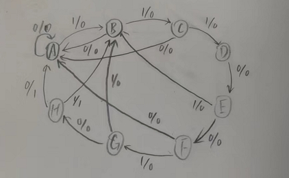
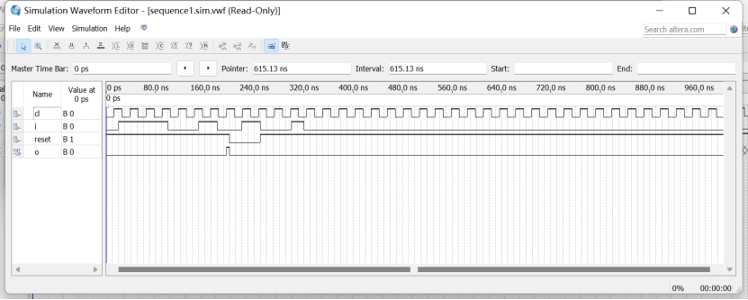
library ieee;
use ieee.std_logic_1164.all;
use ieee.std_logic_unsigned.all;
entity sequence1 is
	port(cl,i,reset:in std_logic;
			o: out std_logic);
end sequence1;

architecture a of sequence1 is
type mytype is (A,B,C,D,E,F,G,H);
signal ty:mytype;
begin
	process(cl,reset)
	begin
		if reset='0' then
			ty<=A;
		elsif cl'event and cl='1' then
			case ty is
				when A=>if i='1' then ty<=B;end if;
				when B=>if i='1' then ty<=C;
					else ty<=A;end if;
				when C=>if i='1' then ty<=D;
					else ty<=A;end if;
				when D=>if i='0' then ty<=E;
					else ty<=B;end if;
				when E=>if i='0' then ty<=F;
					else ty<=B;end if;
				when F=>if i='1' then ty<=G;
					else ty<=A;end if;
				when G=>if i='0' then ty<=H;
					else ty<=B;end if;
				when H=>if i='1' then ty<=B;
					else ty<=A;end if;
			end case;
		end if;
	end process;
	output_p:
	process(ty)
		begin
			case ty is
				when H=>o<='1';
				when others=>o<='0';
			end case;
		end process;
end architecture;
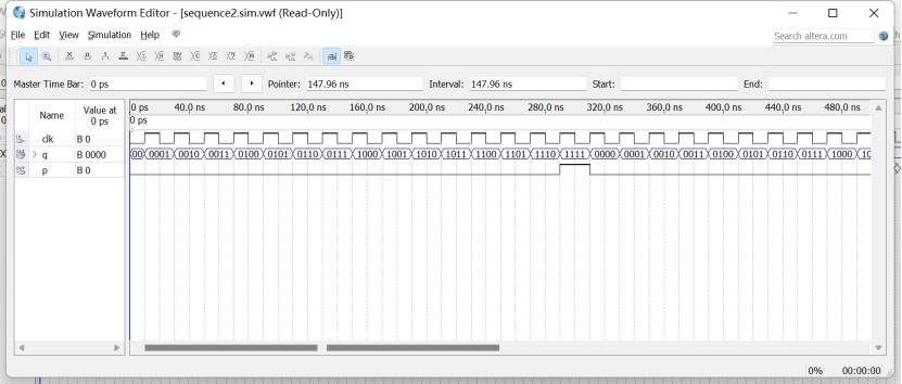
library ieee;
use ieee.std_logic_unsigned.all;
use ieee.std_logic_1164.all;
entity sequence2 is
	port(clk:in std_logic;
			p:out std_logic;
			q:out std_logic_vector(3 downto 0));
end sequence2;
architecture a of sequence2 is
begin
	process(clk)
	variable x:std_logic_vector(3 downto 0);
	begin
		if clk'event and clk='1' then
			if x<"1111" then x:=x+1;
			else x:="0000";
			end if;
		end if;
		if x="1111" then p<='1';
		else p<='0';
		end if;
		q<=x;
	end process;
end architecture;
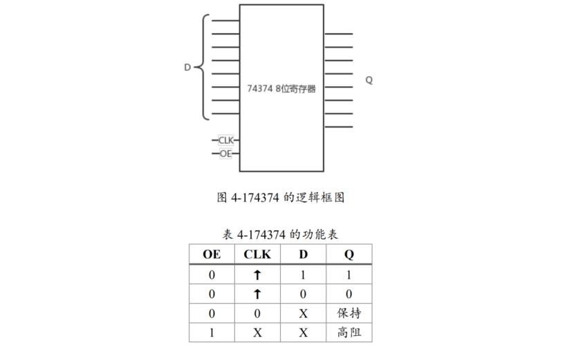
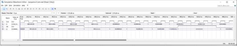
library ieee;
use ieee.std_logic_1164.all;
use ieee.std_logic_unsigned.all;
entity sequence3 is
	port(OE,CLK:in std_logic;
			D:in std_logic_vector(7 downto 0);
			Q:out std_logic_vector(7 downto 0));
end sequence3;
architecture a of sequence3 is
begin
process(CLK,OE,D)
begin
	if OE='1' then
		Q<="11111111";
	elsif CLK'event and CLK='1' then
		Q<=D;
	end if;
end process;
end architecture;

 wechat