实验一 8421码和格雷码的转换

一、 实验内容

利用 VHDL 语言设计一个 4 位 8421 码到 4 位格雷码的编码器。

使用波形图仿真验证其功能。

二、 设计过程

img

img

三、 源代码

1
2
3
4
5
6
7
8
9
10
11
12
13
library ieee;
use ieee.std_logic_1164.all;
entity combination1 is
port(a:in std_logic_vector (3 downto 0);
b:out std_logic_vector (3 downto 0));
end entity combination1;
architecture a of combination1 is
begin
b(0) <= a(0);
b(1) <= a(0) xor a(1);
b(2) <= a(1) xor a(2);
b(3) <= a(2) xor a(3);
end architecture;

四、 仿真验证与实验结果

img

由电路可以看出,满足真值表所要求效果。

实验二 数值比较器

一、 实验内容

数值比较器是对两个位数相同的二进制数进行比较并判定其大小关系的算术运算电路。

使用 if 语句编写对两个 4 位二进制数进行比较的 VHDL 程序,其中 A 和 B 分别是参与比较的两个 4 位二进制数,YA、YB、YC 是用来分别表示 A>B、A<B、A=B 的 3 个输出端。

使用波形图仿真验证其功能。

二、 设计过程

设计两个输入变量的比较器,只需将大于等于小于分三种情况输出即可。

三、 源代码

1
2
3
4
5
6
7
8
9
10
11
12
13
14
15
16
17
18
19
20
21
22
23
24
25
26
library ieee;
use ieee.std_logic_1164.all;
entity combination2 is
port(a,b:in std_logic_vector(3 downto 0);
y1,y2,y3:out std_logic);
end entity combination2;
architecture b of combination2 is
begin
process(a,b)
begin
if(a>b)then
y1 <= '1';
y2 <= '0';
y3 <= '0';
elsif(a=b)then
y1 <= '0';
y2 <= '1';
y3 <= '0';
elsif(a<b)then
y1 <= '0';
y2 <= '0';
y3 <= '1';
end if;
end process;
end architecture;

四、 仿真验证与实验结果

img

为验证实验结果,采用a从0000累加1,b从0000累加4的方法,对比a、b的大小。其中可以观察到,0111|0011时大于端输出1;0100|0100时等于端输出1;0001|0101时小于端,说明实验成功。

实验三 全加器

一、实验内容

把加数、被加数和低位进位逻辑三者加起来的电路称为全加器。其逻辑表达式为

Si=Ai⊕Bi⊕Ci-1,Ci=(Ai⊕Bi)Ci-1+ AiBi。其真值表如下表所示。

img

根据全加器的电路图和真值表,设计一个 VHDL 程序实现全加器。使用波形图仿真验

证其功能

二、设计过程

逻辑表达式已经给出,根据给定逻辑表达式设计电路即可。

三、源代码

1
2
3
4
5
6
7
8
9
10
11
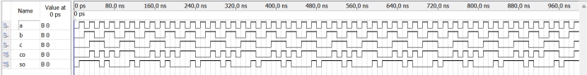
library ieee;
use ieee.std_logic_1164.all;
entity combination3 is
port(a,b,c:in std_logic;
co,so:out std_logic);
end combination3;
architecture a of combination3 is
begin
so<=a xor b xor c;
co<=((a xor b)and c)or(a and b);
end architecture;

四、 仿真验证与实验结果

img

图中各种情况均以表现出来,数值与真值表中相同,说明实验成功。

实验四 3 线-8线译码器

一、实验内容

译码器是一个多输入、多输出的组合逻辑电路。它的作用是把给定的代码进行“翻译”,

变成相应的状态,使输出通道中相应的一路有信号输出。译码器在数字系统中有广泛的用途,

不仅用于代码的转换、终端的数字显示,还用于数据分配、存储器寻址和组合控制信号等,

不同的功能可选用不同种类的译码器。

译码器可分为通用译码器和数码显示译码器两大类,前者又分为变量译码器和代码变换

译码器。

描述一个 3 线-8 线译码器,使能端为 G1、G2A、G2B,地址选择端为 A[2..0],输出端

为总线 Y。

img

二、设计过程

根据给出的真值表,用 case 语句描述电路,利用真值表辅助,使用 VHDL 语言编写出程序。使用波形图仿真验证其功能。

三、源代码

1
2
3
4
5
6
7
8
9
10
11
12
13
14
15
16
17
18
19
20
21
22
23
24
25
26
27
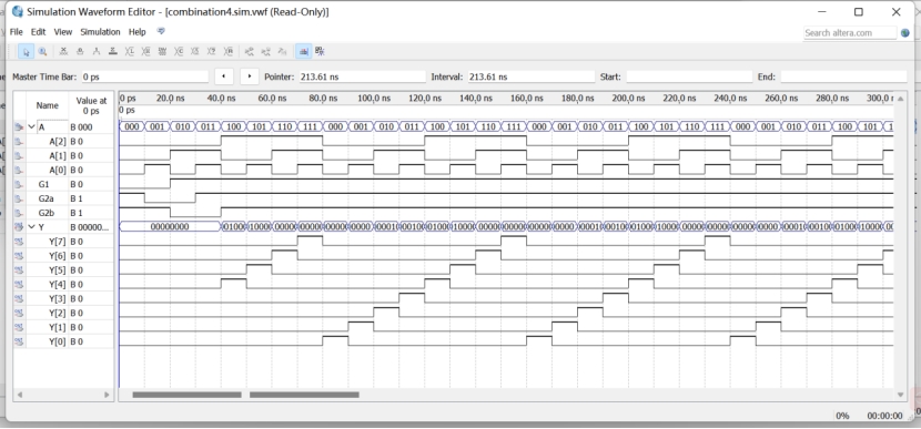
library ieee;
use ieee.std_logic_1164.all;
entity combination4 is
port(G1,G2a,G2b:in std_logic;
A:in std_logic_vector(2 downto 0);
Y:out std_logic_vector(7 downto 0));
end entity combination4;
architecture a of combination4 is
begin
process(A,G1,G2a,G2b)
begin
if(G1='1' and G2a='1' and G2b='1')then
case A is
when "000"=>Y<="00000001";
when "001"=>Y<="00000010";
when "010"=>Y<="00000100";
when "011"=>Y<="00001000";
when "100"=>Y<="00010000";
when "101"=>Y<="00100000";
when "110"=>Y<="01000000";
when "111"=>Y<="10000000";
end case;
else
y<="00000000";
end if;
end process;
end architecture;
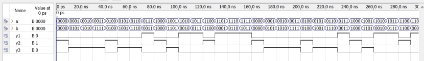
四、 仿真验证与实验结果

img

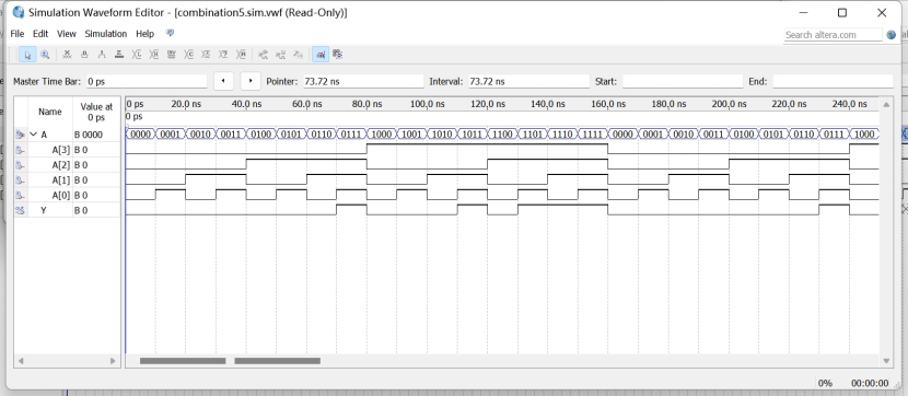
从波形图可以看出输出Y和输入的三位二进制数一一对应,功能实现。

实验五表决器

一、实验内容

用 VHDL 语言设计实现一个 4 人表决器,多数人赞成决议表示通过,否则决议不通过。

使用波形图仿真验证其功能。

二、设计过程

img

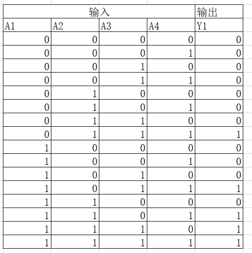
得Y=A1A2A3+A2A3A4+A1A2A4+A1A3A4+A1A2A3A4

三、源代码

1
2
3
4
5
6
7
8
9
10
library ieee;
use ieee.std_logic_1164.all;
entity combination5 is
port(A:in std_logic_vector(3 downto 0);
Y:out std_logic);
end combination5;
architecture a of combination5 is
begin
Y<=(A(0) and A(1) and A(2)) or (A(0) and A(1) and A(3)) or (A(0) and A(3) and A(2)) or (A(3) and A(1) and A(2)) or (A(0) and A(1) and A(2) and A(3));
end architecture;

四、 仿真验证与实验结果

img

如图中信号,当输入用两个以上为1时,输出为1,满足题目要求。